[Proper] Potentiometer Connection and Circuit Diagram ETechnoG
Potentiometer Connection, Circuit Diagram, Wiring Guide Linquip
A potentiometer is a type of variable resistor. These passive components are designed to control electrical resistance, measured in Ohms (Ω). Multiple different variations are available, including trimmer and rotary potentiometers, but the functional principle remains the same.

[Proper] Potentiometer Connection and Circuit Diagram ETechnoG
Table of Contents What is Potentiometer? What are Potentiometers made of? Shared Characteristics of Potentiometers Potentiometer Symbol Construction of Potentiometers Potentiometer Diagram Types of Potentiometer What does a potentiometer do and how does it work? Potentiometer Circuit What is a potentiometer used for?

[Proper] Potentiometer Connection and Circuit Diagram ETechnoG
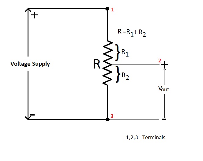
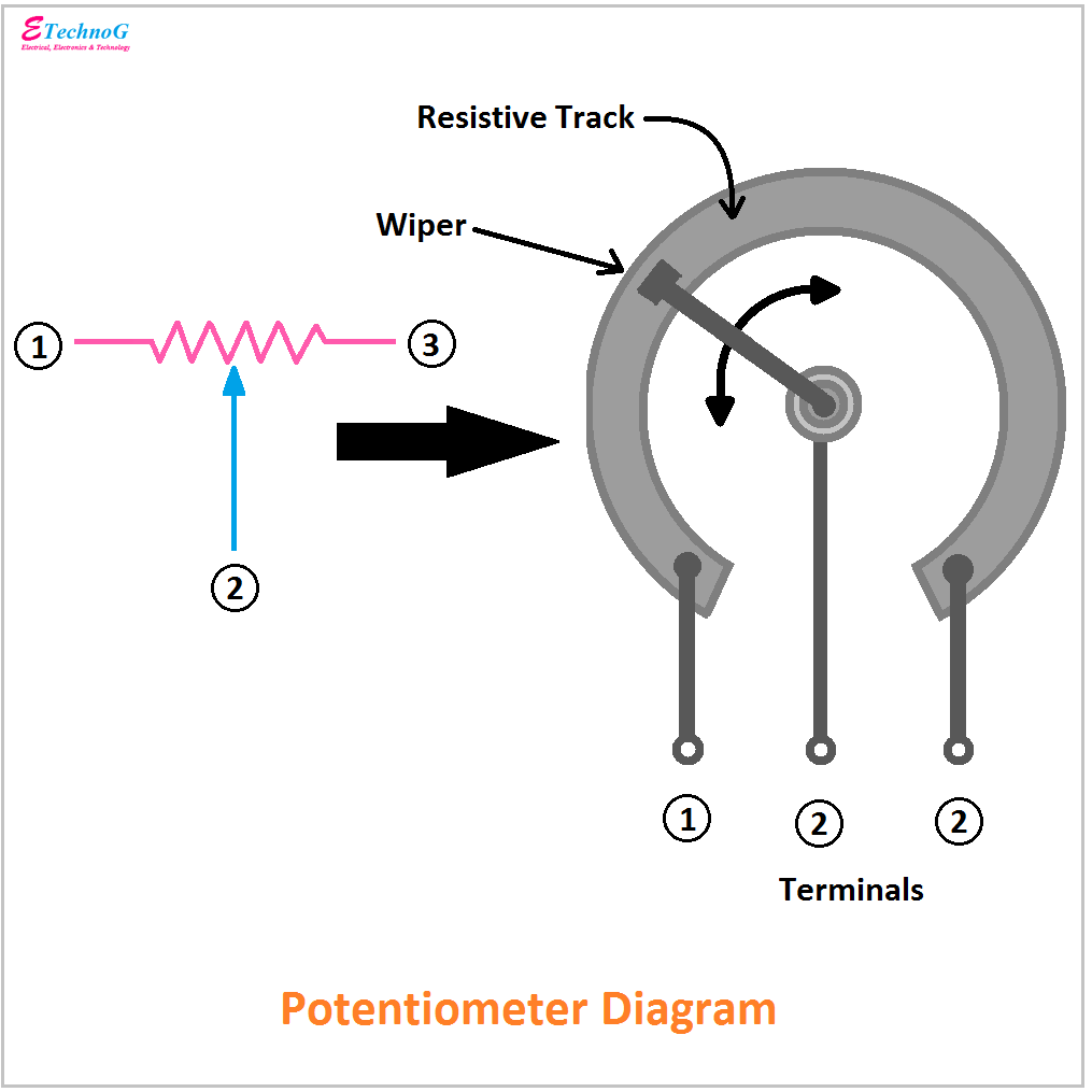
The schematic symbol for a basic potentiometer is shown in Figure 3.8.3 . For convenience, its terminals are labeled A and B for the two ends, and W for the wiper arm. Figure 3.8.3 : Schematic symbol for a potentiometer, with labels. A pot can be visualized as two resistors in sequence with a tap between them. The total resistance never changes.

potentiometer_diagram Electronics Go
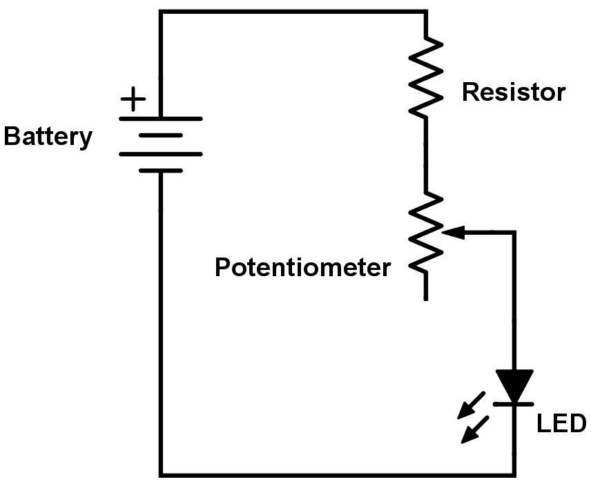
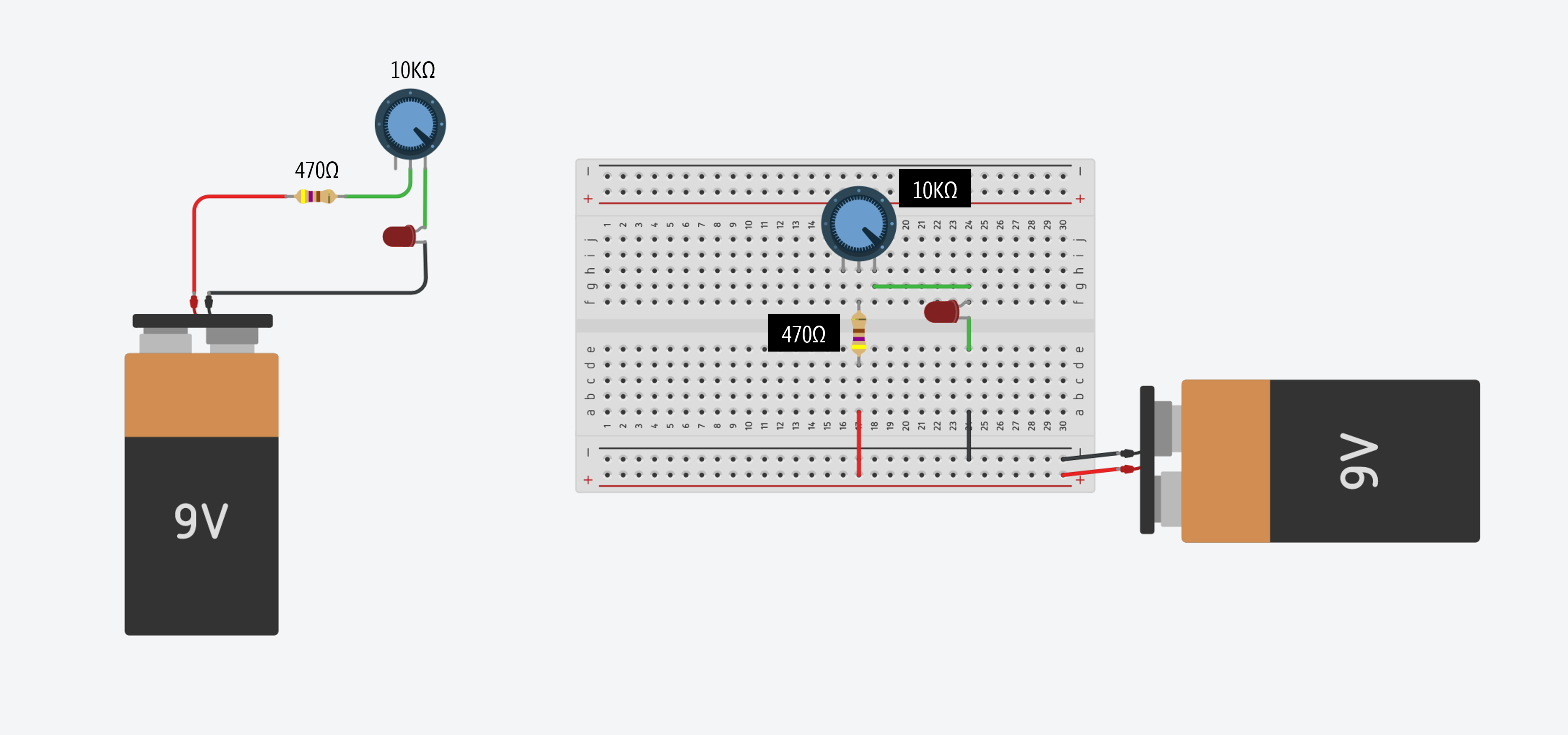
A potentiometer circuit diagram is a graphical representation of the components used in a potentiometer circuit, such as resistors, transistors, and capacitors. The purpose of a potentiometer circuit is to control the voltage level of an electronic signal.
What is Potentiometer? Diagram, Symbols, Characteristics Linquip
Potentiometers are adjustable resistors used in circuits for many things, such as to control the volume of an amplifier, control the brightness of a light, and much more. It is like the resistor. But while the resistance value of a resistor stays the same, you can adjust the resistance value of a potentiometer.
The Potentiometer And Wiring Guide Build Electronic Circuits
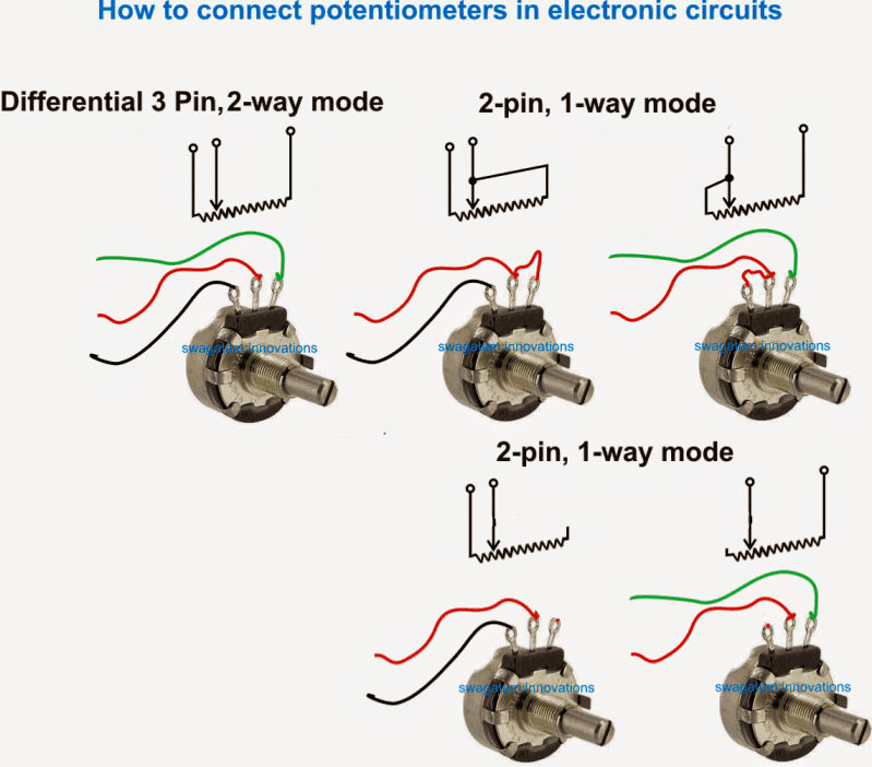
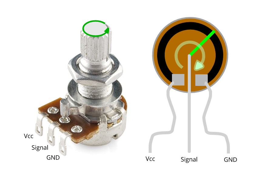
About Potentiometer Rotary potentiometer (also called rotary angle sensor) is used to manually adjust the value of something (e.g volume of the stereo, the brightness of lamp, zoom level of oscilloscope.) Pinout Potentiometer usually has 3 pins: GND pin: needs to be connected to GND (0V) VCC pin: needs to be connected to VCC (5V or 3.3v)
How to Use Potentiometers on the Arduino Circuit Basics
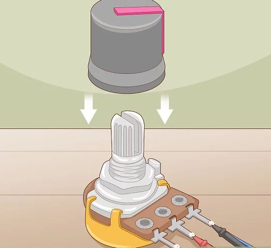
A potentiometer is a simple mechanical device that comes in many different forms. It provides a variable amount of resistance that changes as you manipulate it. The examples in this article uses a potentiometer with a twisting shaft, one of the more common versions of a potentiometer you will find.
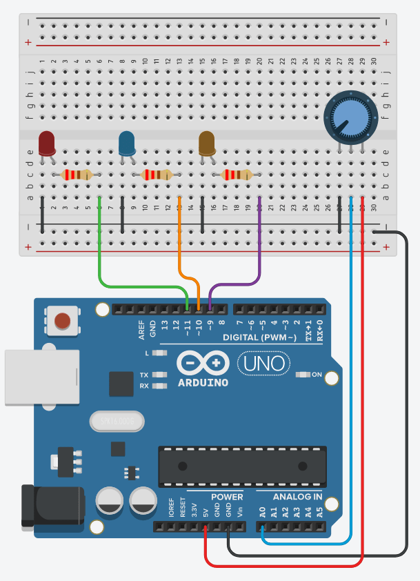
Arduino Potentiometer with Multiple LEDs [Tutorial] The Robotics BackEnd
Potentiometers, often referred to as "pots", are fundamental components in the realm of electrical engineering. These versatile devices play a pivotal role in controlling and measuring electrical signals, providing a dynamic interface between circuits and the physical world they interact with.
Potentiometer Circuit Diagram And Working
The potentiometer, commonly referred to as a "pot", is a three-terminal mechanically operated rotary analogue device which can be found and used in a large variety of electrical and electronic circuits. They are passive devices, meaning they do not require a power supply or additional circuitry in order to perform their basic linear or.
How a Connect a Potentiometer Homemade Circuit Projects
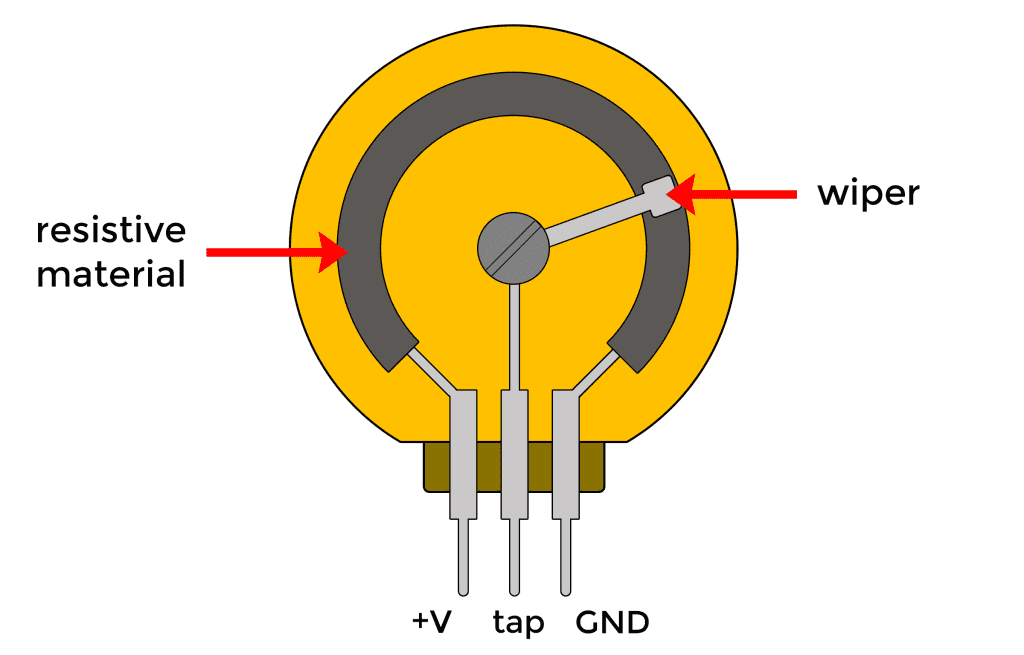
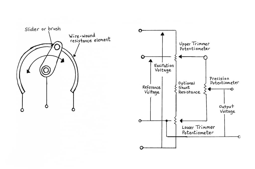
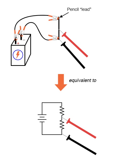
Potentiometers serve as a versatile tool in electronic circuits that allows users to adjust the movement of electrical current. Generally constructed from carbon, conductive plastic, or wire-wound material, they are composed of a resistive element along with an adjustable wiper that slides across it.
Linear Potentiometer Circuit Diagram shockwavetherapy.education
AboutTranscript. Let's explore, logically, the working principle of a slide-wire potentiometer. A potentiometer can measure voltages, with higher accuracy than a voltmeter, without drawing a current from the main circuit. Created by Mahesh Shenoy.
Circuit Diagram Of Potentiometer
Potentiometers, or pots, are a type of resistor used to control the output signal on an electronic device, like a guitar, amplifier, or speaker. They have a small shaft on top that functions like a knob; when the user turns the shaft, it turns the resistance on the signal up or down.
Potentiometers Basic Principles
The measuring instrument called a potentiometer is essentially a voltage divider used for measuring electric potential (voltage); the component is an implementation of the same principle, hence its name. Potentiometers are commonly used to control electrical devices such as volume controls on audio equipment.
Wiring A Potentiometer As A Variable Resistor
In a circuit diagram, a potentiometer is represented by one of the two symbols below: How Does a Potentiometer Work? A potentiometer has 3 pins. Two terminals (the blue and green) are connected to a resistive element and the third terminal (the black one) is connected to an adjustable wiper.

The Arduino Segment Potentiometer with LEDs and "if" commands
The potentiometer has been an essential, passive circuit component from the earliest days of electricity and electronics. It is a three-terminal device with an accessible resistor element, providing a voltage divider function via its user-settable wiper on a rotating shaft.
Potentiometers and the Arduino Uno Tutorial Australia
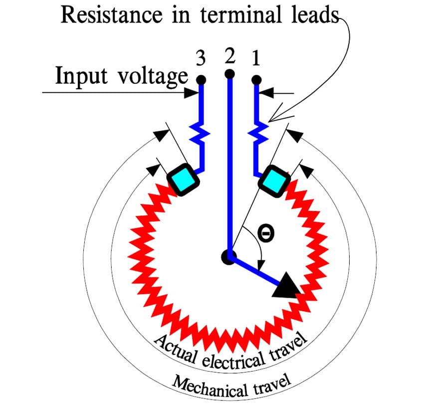
Potentiometer Pinout Diagram. The pinout of the potentiometer varies according to the type of potentiometer like sliding, rotating, or trim.. These pots are fixed in the circuit to make adjustments in the supply voltage. The resistive track in these pots is made of cement or carbon composition. The rotary wiper adjustments can be done with a.
